Architectural drawings are intended to communicate design intentions in a clear manner. This can be best presented with graphic symbols and written forms. Industry standards have been developed to provide a universal language of graphic symbols and written forms for different design companies and building professions. Typical drafting standards and symbols are described below.
Line Types
Along with line weight and quality, there are standards for different types of lines. Each has a definite meaning and is recognized as a typical symbol or object within the building trades industry. Listed below are the standard types of lines that will typically be used in design drawings.
1) Solid Line
Solid lines are used to indicate visible objects that can be seen in plan, elevation or 3D views. Solid lines are also used for leader lines and dimension lines.
2) Dashed Line
Hidden objects or edges are drawn with short dashed lines. These are used to show hidden parts of an object or objects below or behind another object. Dashed lines are also used to indicate shelving or cabinets above a counter. These lines should be in contact at corners and when perpendicular to another line.
3) Movement, Ghost or Phantom Line
These lines are a series of dashes and very short dashes and are used to show movement or imply direction. These typically are used instead of a dashed line to show an alternate position of an object that can be moved. One object would be drawn with a solid line and its alternate position would be dashed or a phantom line. This can include bi-swing doors, the space needed for drawer and cabinet door openings, sliding door opening direction, hinge points for doors and windows in elevation views, etc
4) Leader Line
Leader lines are used to connect notes or references to objects or lines in a drawing. Leader lines start as a solid line and end in an arrow. Leader lines may be drawn at an angle or curved.
5) Break Lines
Break lines are used when the extents of a drawing cannot fit on the size of paper being used for the drawing. It can also be used when you only need to illustrate a portion of a design or a partial view.
6) Center Line
Center lines are used to indicate the center of a plan, object, circle, arc, or any symmetrical object. Use a series of very long and short dashes to create a center line. If two center lines intersect use short dashes at the intersection.
7) Section Line
The section line is used to show a cutaway view of a floor plan. A section cutting all the way through a floor plan is referred to as a full section. The direction of the arrows shows the direction of the section view. The symbols on the end of the section line indicate the drawing number on top and the page number the section will be located on the bottom.
8) Dimension Line
The dimension line is used to show the measurement of an object. It can be used to indicate length, width, diameter, etc. The dimensions are listed in feet and inches on floor plans and elevations. Detail drawings of cabinetry or other custom pieces are dimensioned in inches.
Material Symbols
Material symbols represent the construction materials cut in section. Below is a list of materials and their symbols used on architectural drawings.

Architectural Graphic Symbols
Drawing Symbols For Cross-Reference
1) Section Symbol
Section symbols are used to indicate where sections are cut. The section mark consists of a 1/2″ diameter circle, an arrow that indicates the view direction of sight which is filled solid black, and two numbers. The upper number tells the section number on the sheet and the lower number indicates the sheet number where the section is drawn. Generally a section call-out is composed of two same section marks, one on each end of the cutting plane line.

2) Elevation Symbol
Elevation marks are used to indicate which direction and from which point on the floor plan is drawn. The elevation mark consists of a 1/2″ diameter circle, an arrow that indicates the direction of sight, and two numbers.
The upper number tells the elevation number on the sheet and the lower number indicates the sheet where the elevation is drawn. Elevation marks can be placed at each spot for different elevation views, as shown Figure 14. Or multiple elevation symbols may be used for the elevation views that are drawn from one middle spot of the space.
3 )Detail Symbol
Detail drawings are identified by a detail mark composed of a 1/2” diameter circle and two numbers. The upper number tells the detail number on the sheet and the lower number indicates the sheet number where the detail is drawn. The feature that needs a detail drawing is enclosed in a large circle and connected to the circle of the detail mark with a leader. Detail symbols are used on not only floor plan but also elevation or section drawings.
Also Read: Architectural Drafting and Its Types – A Complete Guide
4) Elevation Datum
Elevation data are used to indicate a level line control point. An elevation datum has three parts. Farthest from the drawing is a ¼” diameter circle with two lines crossing inside horizontally and vertically, and the upper right part and lower left part are filled with solid black.
Above the horizontal line stretched out from the middle of the circle is a description of a point where a level is measured such as ceiling line, grade, or finished floor plan. The actual elevation that is the height of the point is described below the horizontal line. An elevation datum is generally used for exterior elevations.
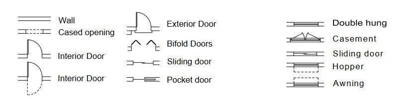
5 )Door Number Symbol
Doors are identified by a door number symbol. A door number symbol has a 3/8” diameter circle and a number inside. The number indicates either door number or door type, depending on the project. The number is then referenced to the door schedule.
6 )Window Letter Symbol
Windows are identified by a window number symbol. A window letter symbol has a 3/8” diameter hexagon and a letter inside. The letter indicates either door number or door type, depending on the project. The letter is then referenced to the window schedule.
You may also like:- Don’t Buy A House In These 5 US Cities
- A Guide to Prepare for Your First Home Purchase
- A Comprehensive Guide to Saving on Major Appliances
- How to Save on Home Improvement – Cost-Effective Tips for Enhancing Your Space
- Practical Tips and Strategies for Saving Money on Furniture Purchases
- 51 House Cleaning Shortcuts to Save Time and Effort
- 5 Signs of a Good Air Duct Cleaning
- Tenant’s Guide – 5 Things to Remember When You Move In
- 7 Simple Reasons Why You Need a Network Security Camera for Your Home
- Fire Safety Checklist for Home – A Comprehensive Guide