Drawing is considered to be a universal language. Drafting is a technical drawing used by designers to graphically present ideas and represent objects necessary for a designed environment.
A set of these drafted illustrations is called a construction document (CD). There are common rules and standards to ensure that all designers are able to understand what is in the drawing. These design drawings use a graphic language to communicate each and every piece of information necessary to convey an idea and ultimately create a design.
The following section of this article will help guide you through the common drafting standards that will be used in the Interior Design programs.
Architectural Drafting
Architectural drafting is basically pictorial images of buildings, interiors, details, or other items that need to be built. These are different from other types of drawings as they are drawn to scale, include accurate measurements and detailed information, and other information necessary to build a structure.
These documents are graphic representations to communicate how to do the construction, remodeling, or installation of a design project. These include drawings for floor plans, elevations, sections, details, ceiling plans, finish schedules, and mechanical information such as electrical, plumbing, air conditioning, and heating plans.
Types of Drafting
There are three categories of drawings in interior design:
- process drawings (preliminary images, sketches, schematics, etc.),
- construction documents (drafted drawings, working drawings, plans, elevations, sections, details, etc.), and
- presentation drawings (illustrated sketches and three-dimensional views including perspectives, obliques, isometrics, etc.).
The main focus of this section is the drafted drawing of which there are also three different types:
- Technical Sketch,
- Mechanical Drafting, and
- CAD (Computer-Aided Drafting)
These all fall under the heading of architectural drafting as they each convey building detail in scale and use of a common graphic language.
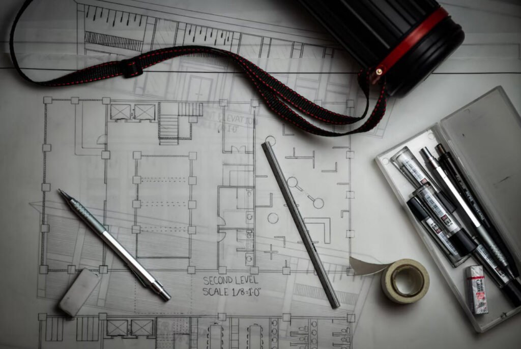
1) Technical Sketch
Like an artist may use sketches to develop ideas for a painting or sculpture, technical sketches are used during the development of ideas for initial or preliminary plans.
The ability to make quick and accurate sketches is a valuable advantage that helps you convey design ideas to others. A sketch may be of an object, an idea of something you are thinking about, or a combination of both. Most of us think of a sketch as a freehand drawing, which is not always the case. You may sketch on graph paper to take advantage of the lined squares, or you may sketch on plain paper with or without the help of drawing instruments.
Technical sketches are drawn without mechanical aid, like a t-square, compass, or straight edge, but, like other forms of architectural drafting, are drawn to scale and contain a variety of line weights and line styles.
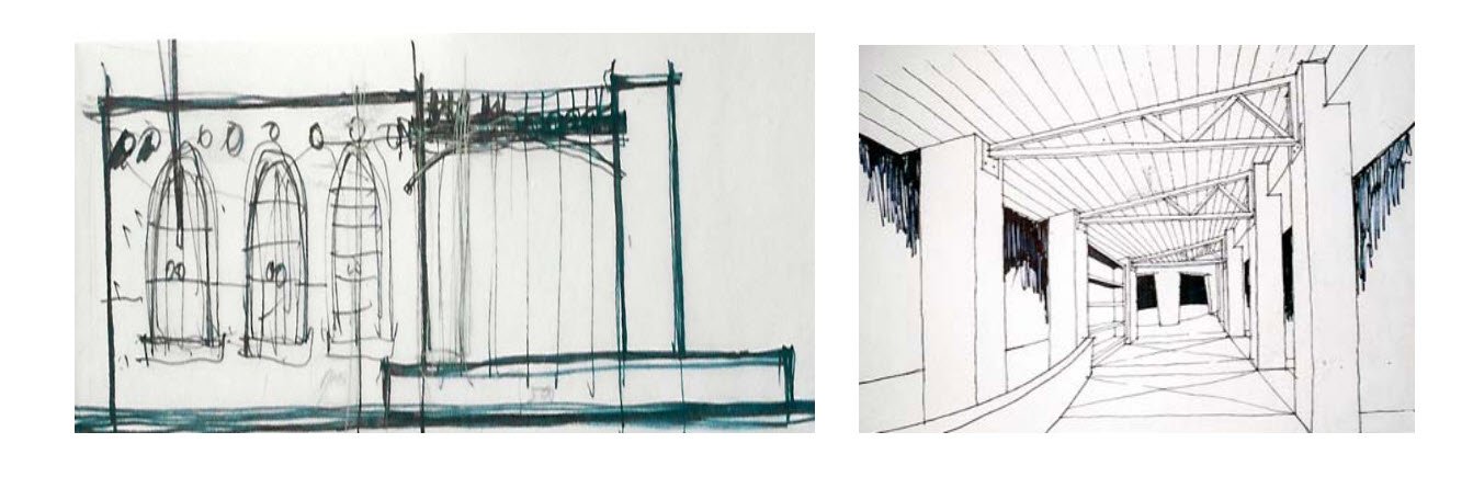
The pencil or pen is guided by the hand of the drafter alone and this is usually done on trace paper over a 1/4″ grid paper. The grid paper becomes the guide helping to keep lines straight. A technical sketch gives an idea that the design is still being developed while a mechanically drafted or CAD drawing implies an advanced state of planning and gives the impression the design has been finalized.
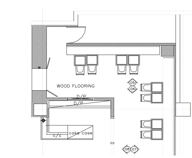
2) Mechanical Drafting
Mechanical drafting is a refined style of drawing in which the pencil or pen is guided by devices such as t-squares, parallel rules, straightedges, compasses, triangles, and French curves.
These drawings are developed only after the conceptual phase of a project has been completed and the design is finalized. However, it is typical to see revisions of construction documents as well as client needs change or other issues arise.
Also Read: Common Drafting Standards and Symbols
The typical set of construction documents consists of mechanical drafted illustrations that include interior and exterior elevations, plans, sections, details and other drawings needed to complete or build a project.
These are used within the professions of interior design, architecture, engineering, and other building trade industries and show construction needs, architectural features, structural elements, electrical and mechanical systems, detail drawings related to structures, and furnishings.
3) Computer Drafting
When drafted documents are prepared on a computer, they are referred to as computer-aided drafting (CAD). An advantage of CAD is the speed of revisions to a document.
Instead of redrafting an entire page alterations can be made quickly and easily and the page reprinted or plotted. CAD drawings can also be easily stored electronically and shipped to other designers who can make revisions or alterations. Some design and drafting work can be completed more quickly on CAD; however, you will still need to use technical or mechanical drafting for design development.
Drafting Media
The papers and films used to draw on are drafting media. While sketching may be done on any size piece of paper or on a variety of types of paper, all forms of architectural drafting, from technical sketching to mechanical drafting, are done on standard sizes and types of paper.
There are two main types of paper, tracing and vellum, and there are drafting films such as Mylar and acetate. Tracing paper and drafting vellum are the two most widely used types of drafting media.
- TRACING PAPER (also called TRACE) is a medium-grade white (or slightly yellow tinted) transparent paper that takes pencil, ink and marker well.
- Trace is typically used for sketching and developing ideas, developing initial and preliminary layouts and developing space planning.
- It is an inexpensive paper and, since it is transparent, a new sheet can be placed over a preliminary drawing to refine it.
- It is easier and neater to do this than to erase and redraw lines on the original.
- Some designers use trace for presentations in the early phase of a design project, then, when the designs are approved and fully developed, they are transferred to vellum.
- DRAFTING VELLUM (also called TRACING VELLUM) is a high-grade white (or slightly tinted) transparent paper that takes pencil well, and from which pencil lines can be easily erased.
- Reproductions can be made directly from pencil drawings on drafting vellum.
- Vellum also takes pen and ink well. On most papers, ink will bleed (that is spread and absorb into the paper).
- Ink lines on vellum are crisp and solid as it does not absorb the ink readily; however, caution must be taken to not unintentionally smear the ink before it dries.
- GRID or GRAPH PAPER is available in a variety of grid patterns.
- Most grid media used in interior design has 4 squares per inch.
- This can represent 1/4″ scale for drawing purposes.
- It is used for planning, drawing, rough design sketching, technical sketches, or simply under a sheet of trace as a guide.
Drafting Sheet Sizes
Most drafting media are available in three styles: rolls, plain sheets, and preprinted sheets with borders and title blocks. There are also sheets available with non-photo blue (a light blue color that does not reproduce when making blueprints) grids. Entry level design projects at the University of Minnesota require the student designer to create borders and title blocks, so plain sheets or rolls will be used primarily throughout the first year.
According to ANSI (American National Standards Institute) in the United States an 8.5 x 11 inch piece of paper is an architectural “A” size sheet. This is typically referred to as letter size.
The “B” size sheets are 11 x 17 and are typically referred to as a “tabloid” size sheet of paper. The “C” size sheets are 18 x 24 inches and the “D” size sheets are 24 x 36 inches. Most drafting for interior design purposes is done on the B, C, and D size sheets.
The decision for choosing a size should be based on project requirements, the scale of the drawings, and the scope and size of the final structure. Trace and vellum may be purchased on rolls that require sizing the paper properly. Trace may be sized by measuring the length needed and using a straight edge, T-square, or parallel rule to rip the paper off of the roll.
Trace rips easily and slightly rough edges are expected. Vellum from a roll should be measured to its proper length and then using a straight edge and an X-acto knife on a proper cutting surfaces trim the paper to its proper length. Scissors should never be used in cutting trace or vellum.
Line Weights
Line weight and line quality are extremely important to a successful set of design drawings. Usually a set of design drawings will go to many different people including the client, other designers or architects, manufacturers, builders, and others within the profession. The lines used for design drawings must be crisp and dark so that they are easy to reproduce and clear copies can be made from them.
The line weight is the light or darkness and width of a line. Manual pencil drafting, drafting in ink, and computer-aided drafting documents must have a variety of line weights. Varied drawing line weights, typically three, should be used on every drawing. These include light, medium, and bold lines.
Aside from these lines used to illustrate a drawing, there are also guidelines and border lines. Guidelines are used for page layout and borderlines are used for framing the page. These different weights technically help to create an easy to understand document and artistically add visual interest to the document.
These documents must also have consistent line quality, which is the uniformity of lines throughout a drawing. These two elements give a sense of professionalism to the documents, provide visual interest, create a clear and easy to read document, and demonstrate the drafting skills and abilities of the designer.
Pencil lines should be solid, uniform in width, and consistent in darkness throughout their length. If a line in a drawing needs to be changed, make sure to erase it cleanly and recreate the line in the appropriate line weight and quality. If only a part of the line needs to be modified, erase using the erasing shield and make sure the new segment and the existing segment match perfectly in width and darkness. Being consistent also applies to pen and ink drawings and CAD drawings.
A pen and ink drawing is usually created first with very light guidelines. When using ink technical or drafting pens, typically the light, medium, and dark weights are created in proportion to one another.
For example, if light is a width of .05, then medium is .1 and dark is .2. The actual width of each line type should also be related to the size and scale of the drawing.
A drawing in 1/4″ scale, like a floor plan, may need smaller pen widths than a drawing in 1-1/2” scale, like a kitchen cabinet drawer detail. The best way to create consistent line weights and line quality is to keep your pencil or pen perpendicular to the drawing surface and drawing media. This keeps the width of the line consistent.
Also, keep a constant pressure as you draw a line type from its start to finish. This takes practice and can be mastered if you focus on creating the line consistently and do not try to rush a drafted document.
Keep in mind the hardness/softness and the diameter of the pencil lead only help control the line weight. You also need to use a consistent amount of pressure on the pencil as you draft to keep each weight of line uniform. If the line seems either too light or too dark try varying the amount of pressure you place on the pencil as you draft. Remember, these drawings are meant to be copied and distributed to a variety of design professionals so the lines need to be crisp and readable.
Lines and Line Quality
- Guidelines or Construction Lines (4H to 6H pencil lead in a .3mm mechanical pencil)
The initial lines that you will draw on your paper are guidelines or what some refer to as construction lines. These lines are temporary and used to lay out the page, create the initial shapes, and provide a guide for lettering heights. The line weight for guidelines is to be very light as they should be almost invisible on the finished drawing.
They must be dark enough for you to see, light enough to erase lines easily, and barely visible when copies or other form of reproductions are made from the drawing. Using a harder 4H to 6H pencil lead in a .3mm mechanical pencil creates the best guidelines. You can also use a blue lead for guidelines as it will not photocopy.
- Bold Lines (soft B to 2B pencil lead in a .5mm or .7mm mechanical pencil)
The primary objects in a drawing should be created using a bold line. Bold lines are very dark and have a thick width. These are created with a .5mm or .7mm mechanical pencil and a soft B to 2B pencil lead.
Walls in plan view and the outline around the perimeter of an elevation or three-dimensional object are examples where bold lines should be used.
- Medium Lines (HB pencil lead in a .5mm mechanical pencil)
Secondary objects such as doors, furnishings, counters, and cabinets should be drawn in a medium line weight. In elevation and 3D views, the perimeter of an object may be drawn in a bold line weight however the information inside the object should be drawn in a medium weight.
Medium line weights are best created using a .5 mm width pencil with HB pencil lead.
- Light Lines (H to 2H pencil lead in a .3mm or .5mm)
Action lines, information lines, and fill patterns should be drawn with light lines. Action lines show potential movement of an object and include door swings in plain view and hinge direction in elevation view.
Information lines convey information about a drawing and include dimension lines, center lines, leader lines, sections lines, and so on. Fill patterns are specific symbols used to indicate a type of material being used.
The light lines can be created with a .5 mm pencil or with a .3 mm pencil and H to 2H pencil leads. It is very important that all of these lines are visible, so do not confuse the term “light” with “hard to see.”
- Border Lines (2B to 4B pencil lead in a .7mm or .9mm pencil)
Border lines are used to create a margin on the drawing sheet and to create the lines around the title block. Border lines should be as dark and about twice as thick as bold lines.
A .7 mm or .9 mm pencil with a 2B to 4B lead works well for creating borderlines. Keep in mind that the softer the lead, B, 2B, etc., the easier it is to smudge the line once it is drawn. For this reason border lines should be the last line drawn on your drafted document.
Line Weights For Lettering
The weight of the lines for lettering varies with the size and scale of the drawing and the visual importance of the lettering. Random notes on the drawing and information from leader lines and dimension lines may be a lightweight line to match the line style. Text within a title block may be medium to bold depending upon its importance.
Likewise, lettering used to label a drawing such as FLOOR PLAN or SOUTH ELEVATION, may need to be medium or bold as well. Within the range of light, medium, and bold line weights, you may also vary the weights slightly as needed to emphasize a part of the drawing.
Typical letting heights are: 3/16”-1/4” for main titles under drawings; 1/8”-3/16” for subtitles and room names; 1/8” for notes and dimensions; and 1/2” for sheet number in the title block.